The NUC6i7KYK is designed to run hot, the heat sink and fan are made to move about 45W max. I decided to see if I could improve the performance of this design by changing the thermal paste on the CPU.
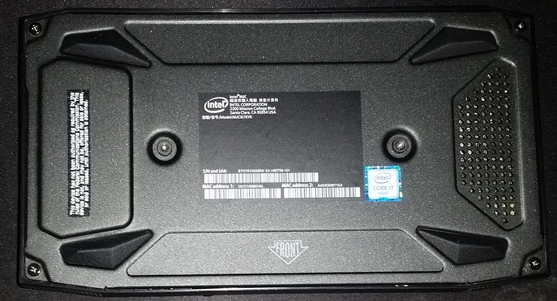
On the base is four screws, remove these screws to remove the bottom plate. I do like that Intel used screws that stays with the base plate.
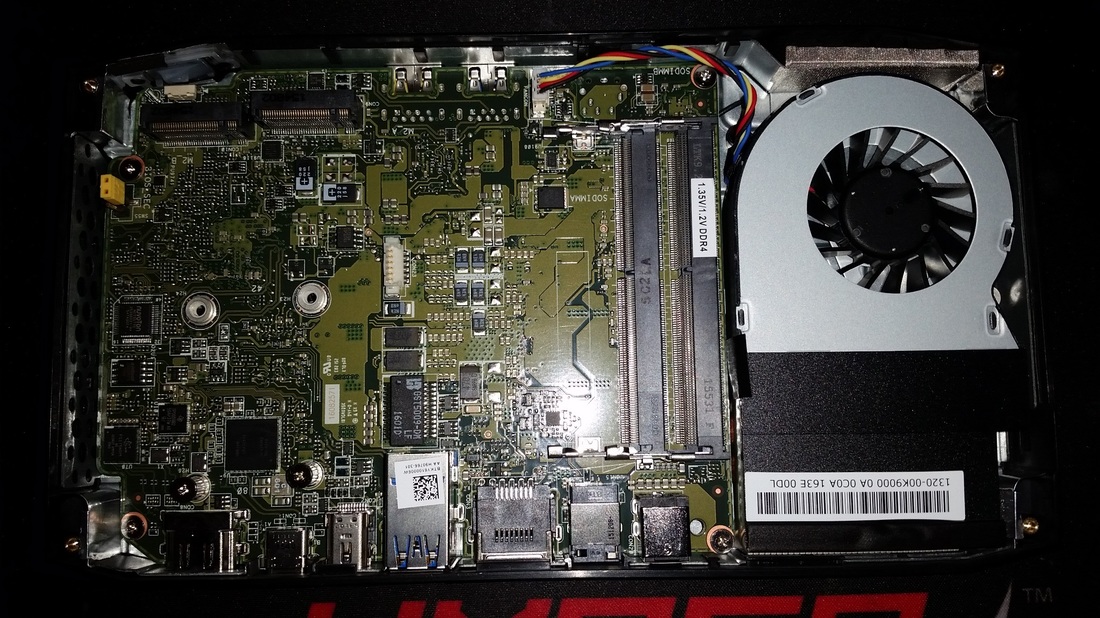
This is the easy to access stuff, you have two M.2 slots and two DDR4 memory slots.
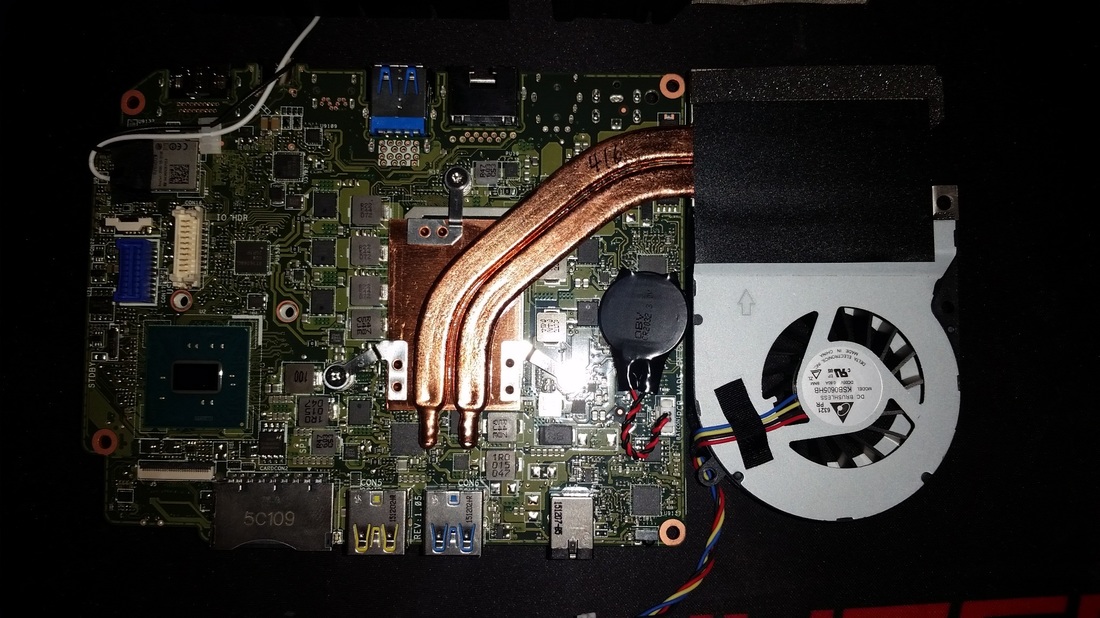
The CPU fan is connected by two thermal pipes that are screwed to the CPU, you must be careful going deeper.
This is the easy to access stuff, you have two M.2 slots and two DDR4 memory slots.
The CPU fan is connected by two thermal pipes that are screwed to the CPU, you must be careful going deeper.
Ok, so once the base plate is off you will need to take off the top cover with the Allen wrench provided, there are four screws in the corners marked with an arrow, remove those four screws and the side plate will be loose enough to removed it.
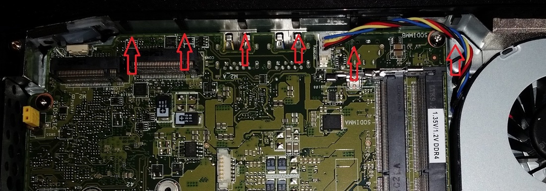
Notice the slots in the metal frame, the slide panel fits down into these grooves, when putting it back together you will see how it makes it easier going back together.
It was pretty easy to get the side off, this must be removed first and installed last. I had to gently coerce it to clear all the connectors on front and back, it was not hard.
Now you need to remove the screws from the bottom side around the outside of the PCB and three more holding down the fan, one is hidden.
Now that you have all the screws out don't go pulling at it, look very closely four posts that the mobo sits on, the front two extend into the mobo and the rear two do not.
Gently lift of the rear of the pcb, the heat sink should move up with it and once you get to the USB ports cleared you can safely lift the front off the posts.
Gently lift of the rear of the pcb, the heat sink should move up with it and once you get to the USB ports cleared you can safely lift the front off the posts.
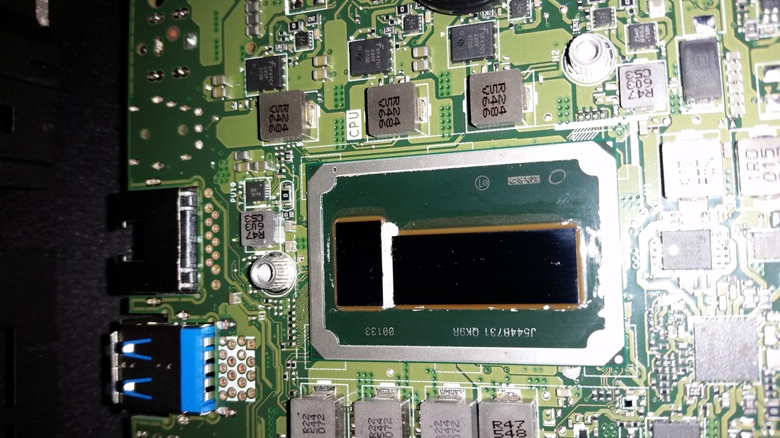
This is what you should be looking at, make sure you are working on a padded anti static surface. You are about to apply pressure to prevent stripping of the CPU screws. And hopefully you did not bend or break the heat pipes.
These screws are special, they are made of butter, so care must be taken.
If you do not have the perfect screw driver then do not continue, you will know when the bit is perfect. Sorry I did not note the model used.
Gently reinforce the backside of the motherboard as you need to press down on the three CPU screws when removing them, I believe there is Loctite on the screws, mine were not easy but I managed not to strip them. I am not kidding, they are made of butter.
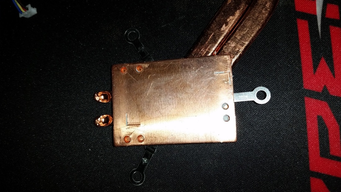
Once the three screws are removed you can gently lift the heat sink free.
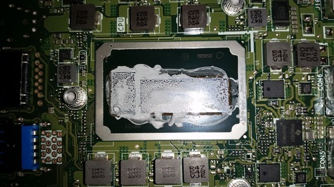
This is the heat sink that is bolted to the CPU and the exposed CPU, the TIM is soft and can be easily cleaned.
These screws are special, they are made of butter, so care must be taken.
If you do not have the perfect screw driver then do not continue, you will know when the bit is perfect. Sorry I did not note the model used.
Gently reinforce the backside of the motherboard as you need to press down on the three CPU screws when removing them, I believe there is Loctite on the screws, mine were not easy but I managed not to strip them. I am not kidding, they are made of butter.
Once the three screws are removed you can gently lift the heat sink free.
This is the heat sink that is bolted to the CPU and the exposed CPU, the TIM is soft and can be easily cleaned.
|
|
By swapping the TIM to Gelid GC-Extreme and it reduced my idle temp by 20c. You can see the contact was good on the original TIM but the TIM quality was sub par for performance.